FMD3000
Network-focused, headless compute. Dual 10GbE SFP+ ports and optional modular AI acceleration.
Compact edge management devices that combine industrial x86 compute, discrete hardware security and an integrated baseboard management controller (BMC). Deploy locally, monitor hardware remotely and maintain access independently of the host operating system.
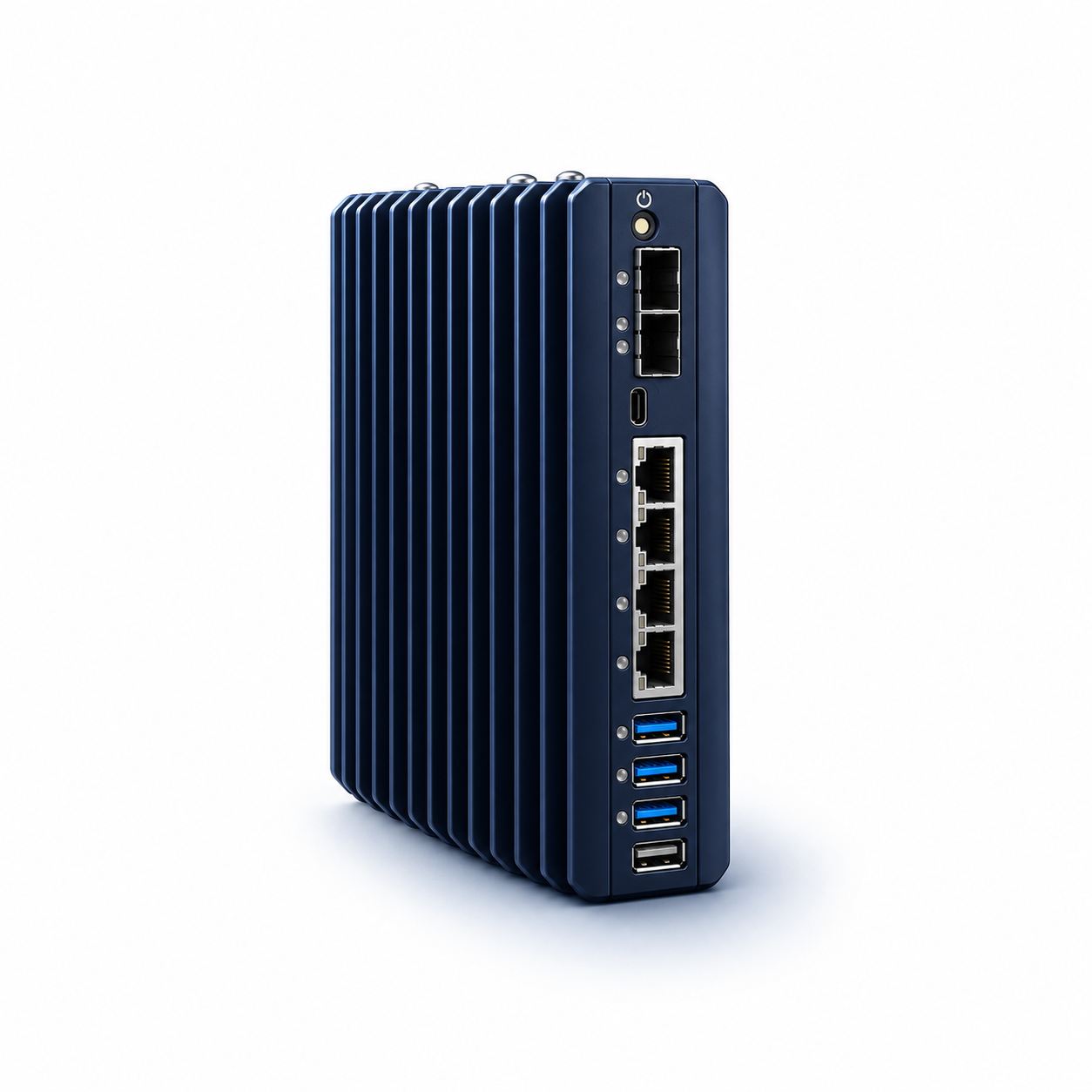
FMD3000 concept rendering in Portal Robotics colors. Illustrative finish; not a dimensional or port-location drawing.
Network-focused, headless compute. Dual 10GbE SFP+ ports and optional modular AI acceleration.
Graphics-capable edge compute. Integrated graphics, dual-display output and native AI acceleration.
Fanless enclosures support compact deployments with configurable memory, storage, wireless connectivity and accelerator options. Optional DIN-rail and rack mounting adapt the platform to different sites. Active-cooled T variants use half-width 1U sleds.
Specification basis: this page describes hardware-platform capabilities, maximums and options. Installed components, operating limits, software integration, availability and services must be confirmed in the final quotation. Optional modules may compete for expansion slots.
An integrated BMC provides out-of-band monitoring and control through its dedicated management connection. The device must retain power and management-network connectivity, including when the host system is shut down or unresponsive.
Use the dedicated 1GbE BMC interface or integrate compatible management software. Host-level tools provide in-band access when the operating system is running; supported methods and Windows limitations depend on the software configuration. Deploy encrypted administrative access and restrict the management network.
Remote hardware diagnostics and recovery can reduce on-site support visits, shorten fault-resolution time and improve control over system power and resources. The controller remains a separate recovery path from host applications.
Both devices include a Mini-USB console interface using an RS232 USB controller, a dedicated management Ethernet port and a remote-power connection. See the I/O reference below.
“Host powered off” refers to the main compute system. Out-of-band functions still require standby power to the management controller and a reachable management network.
Both devices: DDR5 memory; 5600-rated modules operate at 4800 MT/s. Shared operating range: −40°C to 85°C as specified for the platform. Optional DIN-rail and 1U rack mounting. Verify the selected configuration and thermal conditions before deployment. TOPS are maximum platform ratings and do not represent application throughput.
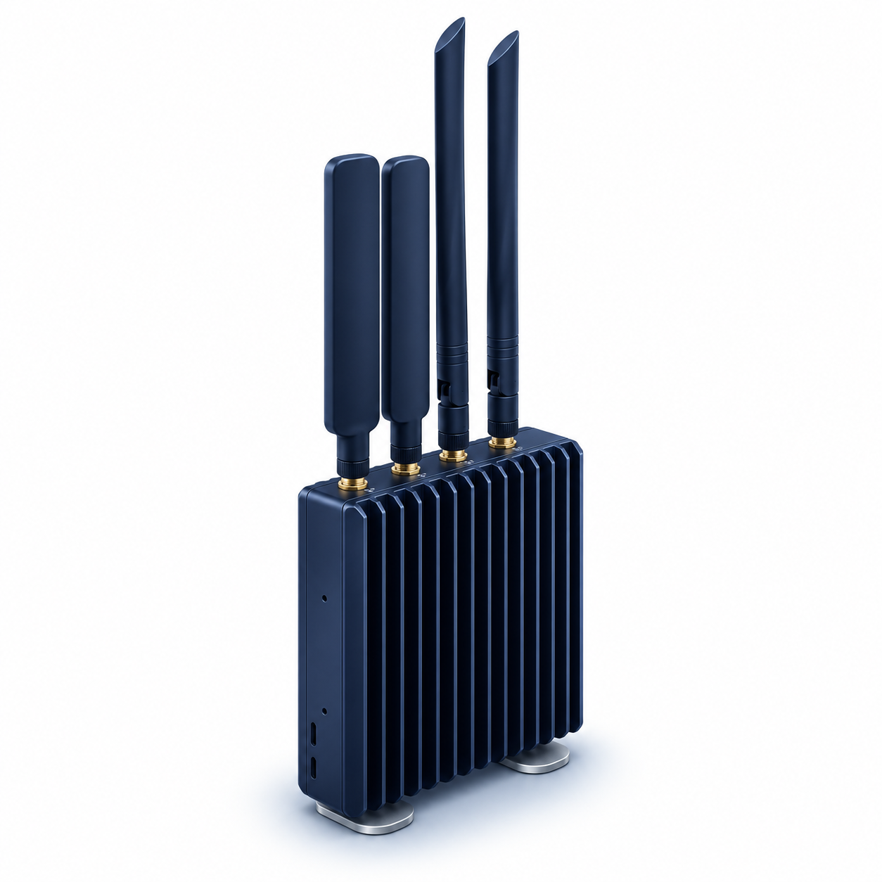
Illustrative rendering · optional wireless configuration shown. Antenna type, quantity and connectivity modules depend on the selected hardware configuration.
Two 10GbE SFP+ interfaces support independent high-bandwidth links. Choose compatible optical or copper transceivers for the cable type and distance. Transceivers are required and are not included. The FMD3200 does not include SFP+ ports.
Both devices use dual-channel DDR5 with two SODIMM slots at 4800 MT/s. Non-ECC capacities include 16, 32, 64, 96 and 128 GB. The FMD3000 additionally supports ECC SODIMMs at 32, 64 or 96 GB; ECC is not supported on the FMD3200.
Up to three M.2 2280 PCIe Gen 4 slots provide a maximum combined storage capacity of 12 TB. Optional AI modules can occupy up to two of these three slots; the 2230 wireless slot can also be used for compatible acceleration. Confirm compatibility for each combination.
Optional 4G LTE or 5G uses a 3042 or 3052 M.2 B-key modem. Two SIM slots support two providers for connectivity planning in areas with variable coverage. Optional wireless LAN and short-range radio are also available.
FMD3000 AI performance depends on the optional accelerator configuration. The FMD3200 includes a native NPU rated up to 16 TOPS and total platform AI performance up to 38 TOPS; compatible modules can add acceleration. These ratings describe different compute scopes and should not be added together as 54 TOPS.
The integrated graphics engine supports up to two displays at 3840 × 2160 resolution and up to 120 Hz. Outputs are a digital video 2.1 connector and USB-C with display 2.1 alternate mode. Confirm cables, displays and firmware for the required mode.
Processor TDP, system consumption and supply rating are different measures. The platform brief describes system draw up to 50 W under load; actual draw depends on configuration and workload. Allow suitable thermal clearance and power margin.
Numbering below follows the platform connector reference. These tables are connection guides rather than physical-scale drawings. Verify the delivered hardware revision before cabling.
The FMD3200 connector illustration identifies four USB-A 3.2 ports, while the summary specification lists three USB 3.2 plus one USB 2.0. Confirm the speed of each delivered USB port before specifying peripherals.
Compliance and services: the hardware brief lists FCC, CE, RoHS and REACH — request current declarations for the ordered configuration. Integration options include BIOS settings, imaging, system configuration and labeling; field deployment management and in-region technical support may be specified by quotation.
A 30-minute walkthrough of VS Platform on your use case: onboarding a node, standing up a secure network, deploying from the catalog, and seeing it all in one portal.